warning light Ram 1500 2013 Get to Know Guide
[x] Cancel search | Manufacturer: RAM, Model Year: 2013, Model line: 1500, Model: Ram 1500 2013Pages: 196, PDF Size: 9.66 MB
Page 3 of 196

INTRODUCTION/WELCOME
WELCOME FROM CHRYSLER
GROUP LLC.................. 3
CONTROLS AT A GLANCE
DRIVER COCKPIT .............. 6
INSTRUMENT CLUSTER .......... 8
GETTING STARTED
KEYFOB ................... 10
KEYLESS ENTER-N-GO™ ......... 11
REMOTE START .............. 13
THEFT ALARM ............... 13
SEATBELT .................. 13
SUPPLEMENTAL RESTRAINT
SYSTEM (SRS) — AIR BAGS ....... 14
CHILD RESTRAINTS ............ 15
FRONT SEATS ................ 20
HEATED/VENTILATED SEATS ....... 22
HEATED STEERING WHEEL ........ 23
TILT STEERING COLUMN ......... 24
OPERATING YOUR VEHICLE
ENGINE BREAK-IN
RECOMMENDATIONS........... 25
TURN SIGNALS/WIPER/WASHER/
HIGH BEAMS LEVER ............ 26
HEADLIGHT SWITCH ............ 27
SPEED CONTROL .............. 28
EIGHT–SPEED AUTOMATIC
TRANSMISSION — IF EQUIPPED .... 29
ELECTRONIC RANGE SELECT (ERS)
OPERATION ................. 30
AIR SUSPENSION SYSTEM ........ 32
MANUAL CLIMATE CONTROLS
WITHOUT TOUCH-SCREEN ........ 34
MANUAL CLIMATE CONTROLS
WITH TOUCH-SCREEN ........... 35
AUTOMATIC CLIMATE CONTROLS
WITH TOUCH-SCREEN ........... 36
PARKSENSE
®REAR PARK ASSIST . . . 37
PARKVIEW®REAR BACK-UP
CAMERA ................... 38
TIRE PRESSURE MONITOR SYSTEM
(TPMS) – 2500 MODELS ONLY ...... 38
POWER SLIDING REAR WINDOW .... 39
POWER SUNROOF ............. 40
WIND BUFFETING ............. 41
ELECTRONICS
YOUR VEHICLE'S SOUND SYSTEM . . . 42
IDENTIFYING YOUR RADIO ........ 44
Uconnect
®Access (AVAILABLE ON
Uconnect®8.4A AND Uconnect®8.4AN)
(IF EQUIPPED) ................ 45
Uconnect
®3.0 ................ 54
Uconnect®5.0 ................ 56 Uconnect
®8.4A ............... 62
Uconnect®8.4AN .............. 79
STEERING WHEEL AUDIO
CONTROLS .................. 97
ELECTRONIC VEHICLE
INFORMATION CENTER (EVIC) ..... 98
PROGRAMMABLE FEATURES ....... 98
UNIVERSAL GARAGE DOOR OPENER
(HomeLink
®) ................ 101
POWER INVERTER ............ 103
POWER OUTLETS ............ 104
OFF-ROAD CAPABILITIES
FOUR WHEEL DRIVE OPERATION . . . 105
UTILITY
TONNEAU COVER............. 108
EASY-OFF TAILGATE ........... 108
PICKUP BOX ................ 109
RAMBOX
®.................. 110
TOWING & PAYLOAD ........... 114
TOW/HAUL MODE ............ 116
INTEGRATED TRAILER BRAKE
MODULE .................. 116
RECREATIONAL TOWING
(BEHIND MOTORHOME, ETC.) ..... 118
DIESEL
DIESEL ENGINE BREAK-IN
RECOMMENDATIONS........... 120
DIESEL ENGINE STARTING
PROCEDURES ............... 120
DIESEL EXHAUST BRAKE
(ENGINE BRAKING) ........... 121
IDLE-UP FEATURE (AUTOMATIC
TRANSMISSION ONLY) ......... 122
ENGINE MOUNTED FUEL
FILTER/WATER SEPARATOR ....... 123
UNDERBODY MOUNTED FUEL
FILTER/WATER SEPARATOR ....... 124
ADDING FUEL – DIESEL ENGINE
ONLY ..................... 125
EXHAUST REGENERATION ....... 125
COOL-DOWN IDLE CHART ........ 127
DIESEL EXHAUST FLUID ........ 127
WHAT TO DO IN EMERGENCIES
ROADSIDE ASSISTANCE......... 130
INSTRUMENT CLUSTER WARNING
LIGHTS ................... 130
IF YOUR ENGINE OVERHEATS ..... 134
JACKING AND TIRE CHANGING .... 135
JUMP-STARTING ............. 148
EMERGENCY TOW HOOKS ....... 150
SHIFT LEVER OVERRIDE ........ 150
TOWING A DISABLED VEHICLE .... 153
FREEING A STUCK VEHICLE ...... 154
EVENT DATA RECORDER (EDR) .... 155
TABLE OF CONTENTS
Page 10 of 196

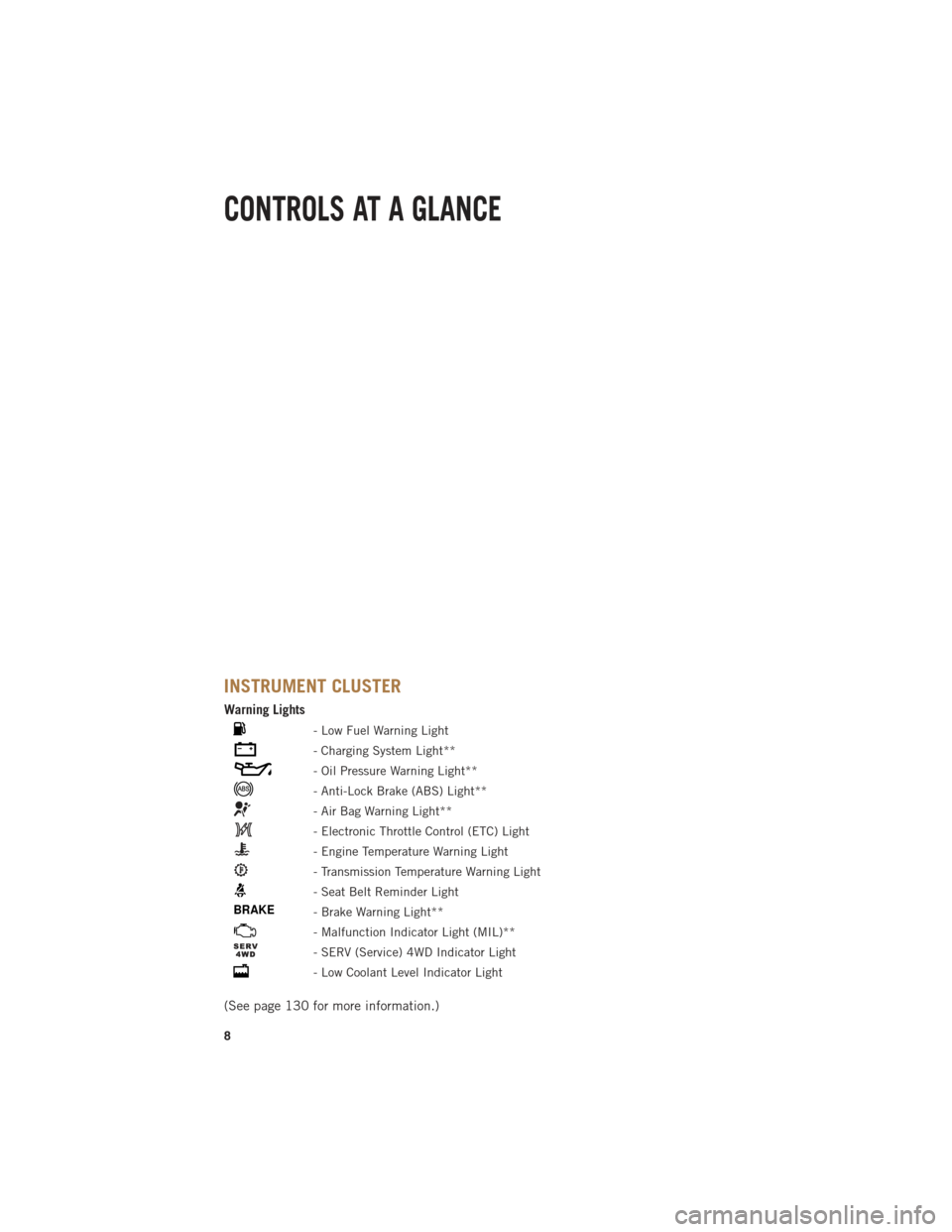
INSTRUMENT CLUSTER
Warning Lights
- Low Fuel Warning Light
- Charging System Light**
- Oil Pressure Warning Light**
- Anti-Lock Brake (ABS) Light**
- Air Bag Warning Light**
- Electronic Throttle Control (ETC) Light
- Engine Temperature Warning Light
- Transmission Temperature Warning Light
- Seat Belt Reminder Light
BRAKE- Brake Warning Light**
- Malfunction Indicator Light (MIL)**
- SERV (Service) 4WD Indicator Light
- Low Coolant Level Indicator Light
(See page 130 for more information.)
CONTROLS AT A GLANCE
8
Page 12 of 196

KEY FOB
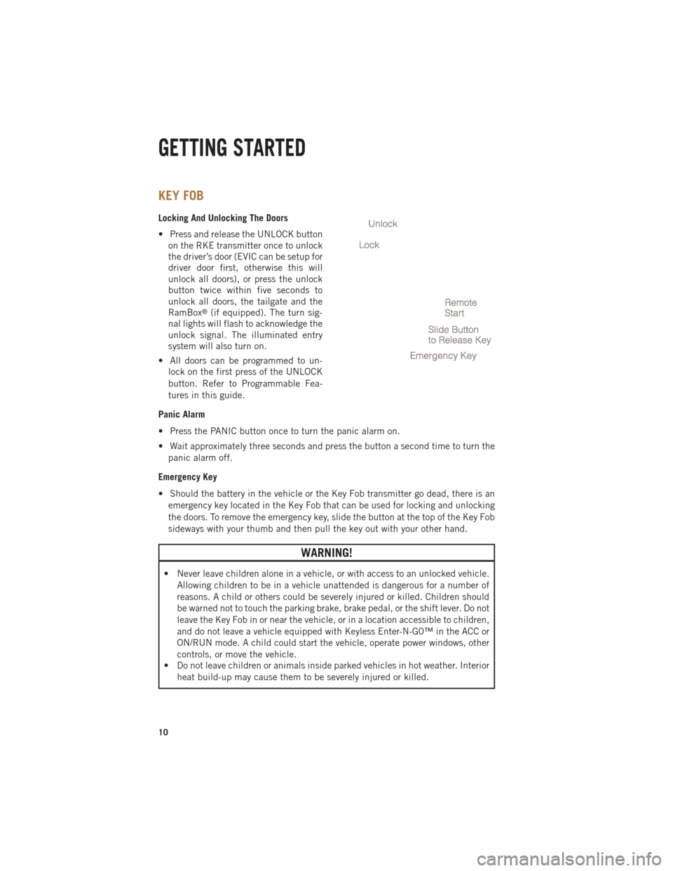
Locking And Unlocking The Doors
• Press and release the UNLOCK buttonon the RKE transmitter once to unlock
the driver’s door (EVIC can be setup for
driver door first, otherwise this will
unlock all doors), or press the unlock
button twice within five seconds to
unlock all doors, the tailgate and the
RamBox
®(if equipped). The turn sig-
nal lights will flash to acknowledge the
unlock signal. The illuminated entry
system will also turn on.
• All doors can be programmed to un- lock on the first press of the UNLOCK
button. Refer to Programmable Fea-
tures in this guide.
Panic Alarm
• Press the PANIC button once to turn the panic alarm on.
• Wait approximately three seconds and press the button a second time to turn the panic alarm off.
Emergency Key
• Should the battery in the vehicle or the Key Fob transmitter go dead, there is an emergency key located in the Key Fob that can be used for locking and unlocking
the doors. To remove the emergency key, slide the button at the top of the Key Fob
sideways with your thumb and then pull the key out with your other hand.
WARNING!
• Never leave children alone in a vehicle, or with access to an unlocked vehicle. Allowing children to be in a vehicle unattended is dangerous for a number of
reasons. A child or others could be severely injured or killed. Children should
be warned not to touch the parking brake, brake pedal, or the shift lever. Do not
leave the Key Fob in or near the vehicle, or in a location accessible to children,
and do not leave a vehicle equipped with Keyless Enter-N-G0™ in the ACC or
ON/RUN mode. A child could start the vehicle, operate power windows, other
controls, or move the vehicle.
• Do not leave children or animals inside parked vehicles in hot weather. Interior
heat build-up may cause them to be severely injured or killed.
GETTING STARTED
10
Page 16 of 196

•A belt that is too loose will not protect you properly. In a sudden stop you could move
too far forward, increasing the possibility of injury. Wear your seat belt snugly.
• A frayed or torn belt could rip apart in a collision and leave you with no protection. Inspect the belt system periodically, checking for cuts, frays, or loose parts.
Damaged parts must be replaced immediately. Do not disassemble or modify the
system. Seat belt assemblies must be replaced after a collision if they have been
damaged (bent retractor, torn webbing, etc.).
• The seat belts for both front seating positions are equipped with pretensioning devices that are designed to remove slack from the seat belt in the event of a
collision.
• A deployed pretensioner or a deployed air bag must be replaced immediately.
WARNING!
In a collision, you and your passengers can suffer much greater injuries if you are
not buckled up properly. You can strike the interior of your vehicle or other
passengers, or you can be thrown out of the vehicle. Always be sure you and others
in your vehicle are buckled up properly.
SUPPLEMENTAL RESTRAINT SYSTEM (SRS) — AIR BAGS
• This vehicle has Advanced Front Air Bags for both the driver and right front passenger as a supplement to the seat belt restraint system. The Advanced Front
Air Bags will not deploy in every type of collision.
• Advanced Front Air Bags are designed to provide additional protection by supplementing the seat belts in certain frontal collisions depending on several
factors, including the severity and type of collision. Advanced Front Air Bags are
not expected to reduce the risk of injury in rear, side, or rollover collisions.
• This vehicle is equipped with Supplemental Side Air Bag Inflatable Curtains to protect the driver, front and rear passengers sitting next to a window.
• This vehicle is equipped with Supplemental Seat-Mounted Side Air Bags to provide enhanced protection to help protect an occupant during a side impact.
•
If the Air Bag Warning Lightis not on during starting, stays on, or turns on while
driving, have the vehicle serviced by an authorized service center immediately.
•Refer to the Owner's Manual on the DVD for further details regarding the Supple-
mental Restraint System (SRS).
GETTING STARTED
14
Page 39 of 196

Air Conditioning (A/C)
• If the air conditioning button is pressed while in AUTO mode, the system will exitAUTO mode and stay in A/C. The mode and blower will be set at the closest mode
and blower position that the system was operating in AUTO.
SYNC Temperature Soft-Key
• Touch the SYNC soft-key on the Uconnect
®Access radio to control the driver and
passenger temperatures simultaneously. Touch the SYNC soft-key a second time to
control the temperatures individually.
Air Recirculation
• Use recirculation for maximum A/C operation.
• For window defogging, turn the recirculation button off.
• If the Recirculation button is pushed while in the AUTO mode, the indicator light may flash three times to indicate the cabin air is being controlled automatically.
Heated Mirrors
• The mirrors are heated to melt frost or ice. This feature is activated whenever you turn on the defroster.
PARKSENSE® REAR PARK ASSIST
• If an object is detected behind the rear bumper while the vehicle is in REVERSE,a warning will display in the instrument cluster and a tone, that changes speed
depending on the distance of the object from the bumper, will sound.
Service The ParkSense® Rear Park Assist System
• When the ParkSense
®Rear Park Assist System is malfunctioning, the instrument
cluster will actuate a single chime, once per ignition cycle, and it will display the
“CLEAN PARK ASSIST SENSORS” or the “SERVICE PARK ASSIST SYSTEM”
message.
• If “CLEAN PARK ASSIST SENSORS” appears in the Electronic Vehicle Informa- tion Center (EVIC) and the rear fascia/bumper is clean and clear of snow, ice, mud,
dirt or other obstruction, see your authorized dealer.
• If “SERVICE PARK ASSIST SYSTEM” appears in the EVIC, see your authorized dealer.
Enable/Disable ParkSense®
• ParkSense
®can be enabled and disabled with a switch located in the switch bank
of the instrument panel or through the Customer-Programmable Features section
of the EVIC. When the switch is pressed to disable the system, the instrument
cluster will display the “PARK ASSIST SYSTEM OFF” message for approximately
five seconds.
OPERATING YOUR VEHICLE
37
Page 40 of 196

PARKVIEW® REAR BACK-UP CAMERA
• You can see an on-screen image of the rear surroundings of your vehicle wheneverthe shift lever is put into REVERSE. The ParkView®Rear Back-Up Camera image
will be displayed in the rearview mirror or touchscreen display along with a caution
note to “check entire surroundings” across the top of the screen. After five seconds
this note will disappear.
• If the rearview mirror or touchscreen display appears foggy, clean the ParkView
®
camera located to the left of the tailgate handle.
WARNING!
Drivers must be careful when backing up; even when using the ParkView®Rear
Back-Up Camera. Always check carefully behind your vehicle, and be sure to
check for pedestrians, animals, other vehicles, obstructions, or blind spots before
backing up. You must continue to pay attention while backing up. Failure to do so
can result in serious injury or death.
TIRE PRESSURE MONITOR SYSTEM (TPMS) – 2500 MODELS
ONLY
Tire Light Load Inflation Switch Description
•
The Tire Pressure Monitoring System on your vehicle has two different tire pressure
settings based on vehicle loading. The Tire Light Load Switch is located on the
Instrument Panel below the climate controls.
• The “Light Load Inflation” and “Max Load Inflation” tire pressures recommended for your vehicle based on vehicle loading are found on the Supplemental Tire
Pressure Information Label located on the rear face of the driver front door.
•
When the vehicle is in the “Light Load Inflation” setting, the Tire Light Load Inflation
switch is On. The indicator light is Off when in the “Max Load Inflation” setting.
Light Load Inflation (Indicator Light On)
• If the passenger and cargo weights are less than the Light Load Pressure Definition shown on the Supplemental Tire Pressure Information Label, inflate or
deflate tires to the correct “Light Load Inflation” pressure. If the indicator light is
not on, the mode can be changed by pushing the switch once.
• If the light on the switch flashes On and Off, after the button is pressed to switch
between modes, this indicates conditions are not correct to switch modes. The system
will not allow switching modes until the tire pressures have been set to Light Load
Inflation as indicated on the Supplemental Tire Pressure Information Label.
OPERATING YOUR VEHICLE
38
Page 41 of 196

•IF THE LIGHT STARTS FLASHING TO SHOW LOW AIR PRESSURE, BRING THE AIR
PRESSURE IN THAT TIRE TO THE PLACARD VALUE SHOWN ON THE LABEL ON THE
DRIVER DOOR. NOTE: AFTER INFLATION, THE VEHICLE MAY NEED TO BE DRIVEN FOR UP
TO 20 MINUTES BEFORE THE FLASHING LIGHT WILL GO OFF.
Max Load Inflation (Indicator Light Off)
• If the passenger and cargo weights exceed the Light Load Pressure Definition shown on the Supplemental Tire Pressure Information Label, adjust tires to the
correct “Max Load Inflation” pressure. If the indicator is on, reset by pushing the
switch once.
• If the tire pressure monitoring light and a “low tire” message appears in the cluster, inflate the tire pressures to the “Max Load Inflation” setting as indicated
in the Supplemental Tire Pressure Information Label.
• After any tire pressure adjustment, the vehicle may need to be driven for up to
20 minutes at speeds over 15 mph for the tire pressure information to be updated, or for
a low tire pressure warning to go out.
• For additional information, refer to the Owner's Manual on the DVD.
POWER SLIDING REAR WINDOW
• The switch for the power sliding rear window is located on the overhead con-
sole.
• Push the switch right to open the glass and pull the switch left to close the
glass.
OPERATING YOUR VEHICLE
39
Page 55 of 196

4.Voice Texting – Use the sound of your voice to create, listen to and send text
messages. Just tell Uconnect®what you want the message to say - it will convert
your voice to text and send the message at your command. Powerful, cloud-based
voice recognition allows you to dictate free form text messages, and send them
from your Bluetooth - enabled phone without taking your hands of the wheel or
focus from the road. Requires a cell phone that supports Bluetooth Message
Access Profile (MAP).
WARNING!
• ALWAYS drive safely with your hands on the steering wheel. You have full responsibility and assume all risks related to the use of the Uconnect®features
and applications in this vehicle. Only use Uconnect®when it is safe to do so.
Failure to do so may result in an accident involving serious injury or death.
• Ignoring the Rearview Mirror light could mean you may not have 9-1-1 Call
service when you need it. If the Rearview Mirror light is illuminated, have an
authorized dealer service the 9-1-1 Call system immediately.
• The Occupant Restraint Controller (ORC) turns on the Air Bag Warning Light on
the instrument panel if a malfunction is detected in any part of the air bag
system. If the Air Bag Warning Light is illuminated, the air bag system may not
be working properly and the 9-1-1 system may not be able to send a signal to
a 9-1-1 operator. If the Air Bag Warning Light is illuminated, have an
authorized dealer service your vehicle immediately.
• If anyone in the vehicle could be in danger (e.g., fire or smoke is visible,
dangerous road conditions or location), do not wait for voice contact from a
9-1-1 operator. All occupants should exit the vehicle immediately and move to
a safe location.
• The 9-1-1 Call system is embedded into the vehicle’s electrical system. Do not
add any aftermarket electrical equipment to the vehicle’s electrical system.
This may prevent your vehicle from sending a signal to initiate an emergency
call. To avoid interference that can cause the 9-1-1 Call system to fail, never
add aftermarket equipment (e.g., two-way mobile radio, CB radio, data
recorder, etc.) to your vehicle’s electrical system or modify the antennas on
your vehicle. IF YOUR VEHICLE LOSES BATTERY POWER FOR ANY REASON
(INCLUDING DURING OR AFTER AN ACCIDENT), THE UCONNECT
®FEA-
TURES, APPS AND SERVICES, AMONG OTHERS, WILL NOT OPERATE.
ELECTRONICS
53
Page 105 of 196

Using HomeLink®
• To operate, press and release the programmed HomeLink
®button. Activation will
now occur for the programmed device (i.e., garage door opener, gate operator,
security system, entry door lock, home/office lighting, etc.,). The hand-held
transmitter of the device may also be used at any time.
WARNING!
• Your motorized door or gate will open and close while you are programming the universal transceiver. Do not program the transceiver if people or pets are in the
path of the door or gate.
• Do not run your vehicle in a closed garage or confined area while programming
the transceiver. Exhaust gas from your vehicle contains Carbon Monoxide (CO)
which is odorless and colorless. Carbon Monoxide is poisonous when inhaled
and can cause you and others to be severely injured or killed.
POWER INVERTER
• A 115 Volt, 150 Watt power inverteroutlet is located on the lower instru-
ment panel next to the climate control
knob. This outlet can power cellular
phones, electronics and other low
power devices requiring power up to
150 Watts.
• To turn on the power outlet, simply plug in the device. The outlet auto-
matically turns off when the device is
unplugged.
NOTE:
The power inverter is designed with
built-in overload protection. If the power
rating of 150 Watts is exceeded, the
power inverter will automatically shut down. Once the electrical device has been
removed from the outlet, the inverter should automatically reset.
WARNING!
To Avoid Serious Injury or Death DO NOT:
• insert any objects into the receptacles
• touch with wet hands
Close the lid when not in use. If this outlet is mishandled, it may cause an electric
shock and failure.
ELECTRONICS
103
Page 115 of 196

CAUTION!
• Failure to follow the following items could cause damage to the vehicle:• Assure that all cargo inside the storage bins is properly secured.
• Do not exceed cargo weight rating of 150 lb (68 kg) per bin.
• Leaving the lid open for extended periods of time could cause the vehiclebattery to discharge. If the lid is required to stay open for extended periods
of time, it is recommended that the bin lights be turned off manually using
the on/off switch.
• Ensure cargo bin lids are closed and latched before moving or driving
vehicle.
• Loads applied to the top of the bin lid should be minimized to prevent
damage to the lid and latching/hinging mechanisms.
• Damage to the RamBox
®bin may occur due to heavy/sharp objects placed
in bin that shift due to vehicle motion. In order to minimize potential for
damage, secure all cargo to prevent movement and protect inside surfaces
of bin from heavy/sharp objects with appropriate padding.
• The maximum load per cleat should not exceed 250 lbs (113 kg) and the
angle of the load on each cleat should not exceed 60 degrees above
horizontal, or damage to the cleat or cleat rail may occur.
WARNING!
•Always close the storage bin covers when your vehicle is unattended or in motion.
• Do not allow children to have access to the storage bins. Once in the storagebin, young children may not be able to escape. If trapped in the storage bin,
children can die from suffocation or heat stroke.
• In a collision, serious injury could result if the storage bin covers are not
properly latched.
• Do not use a storage bin latch as a tie down.
• To reduce the risk of potential injury or property damage:
• Cargo must be secured.
• Do not exceed cargo load rating of your vehicle.
• Secure all loads to truck utilizing cargo tie-downs.
• Extender should not be used as cargo tie-down.
•
When vehicle is in motion do not exceed 150 lbs (68 kg) load on the tailgate.
• The bed extender is not intended for off road use.
•
When not in use, the extender/divider should be in stowed or divider position
with the tailgate closed.
• When in use, all handles are to be in the locked position.
UTILITY
113